SDC has assembled these easy-to-use calculators to assist security dealers, installers, integrators and consultants with designing, specifying and installing electrified access control hardware for their projects.
Ninety percent or more of common installation and operating problems can be avoided by simply ensuring the electrified access control hardware is receiving the power it needs to perform as expected.
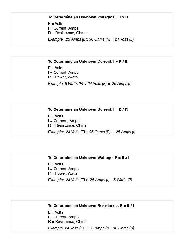
These calculators use algorithms based on Ohm's Law - a formula used to calculate the relationship between voltage, current and resistance in an electrical circuit.
Enter any 3 values to calculate the 4th value in the Voltage Drop and Power Calculators. Enter any 2 values to calculate the 3rd value in the Battery Power Calculator.
We do not recommend wire runs exceeding 1,000 ft. The Voltage Drop Calculator will only provide a Wire Run Length value up to 999 ft.

WIRE GAUGE SIZE & DISTANCE CALCULATORS
For 12V and 24V AC/DC
In real world hardware installations, SDC recommends that you plan for a minimum 5% (or more) Voltage Drop with any electrified access control component. These calculators will determine the maximum distance allowable for a 5% Voltage Drop from the power supply to the furthest load on one circuit.
Enter both Load (between .125 and 6 Amps) and Length (25 - 350 Ft.) values to calculate Wire Gauge Size. For both 12V and 24V Calculators, entering values that will exceed minimum Wire Gauge Size upon calculation, the result will be "Value of minimum wire gauge Not Available." You will need to either reduce the Load and/or the Length values to get a result.

To determine the correct wire gauge to use on one circuit the following information is required:
- The quantity, voltage and current draw of all lock(s) and other powered devices on one circuit.
- The distance in feet from the power supply to the furthest lock.
Add together the current draw (amps) of all locks on the same circuit. "One circuit" implies that two wires are being run from the power supply to one or more locks in parallel.
If the wire gauge size or maximum distance is inadequate for your application, divide the quantity of locks on that circuit to create two or more separate circuits and use calculator to figure each new circuit independently. SDC recommends that two fuse protected circuits be provided for each opening, one circuit for the locking device (inductive loads) and one circuit for access controllers and signaling devices (resistive loads). This allows for significantly smaller gauge wire, increased distance and protects access control and signaling devices from potential damage caused by inductive load devices. All wiring must be installed in accordance with all state and local codes.
OHM'S LAW

Ohm's law states that the current through a conductor between two points is directly proportional to the voltage across the two points.